/

N4 Bacnet Control Systems

N4 Controls Systems

*The complete case study is best viewed on desktop or tablet. This mobile version is abridged.

GUI Design

HVAC Controls

IoT Devices

Job Summary
My Role

GUI Designer

Skills

Budgeting, contracting and hiring, data visualization, engineering drawing analysis, equipment diagram analysis, UX research, UI design

Team

Controls programmers, technicians, contract civil engineers and CAD designers

Employer

Air Conditioning Solutions Inc.

Timeline

November 2018 - January 2020

Deliverable

HVAC Controls Systems

Key Takeaways

Problem

How might we redesign the outdated user interface (UI) of the company's building automation control network (BacNET) systems?

Solution

Designed and implement a comprehensive overhaul of the company's build BacNET UI.

Impact

The new GUI garnered high satisfaction among customers and coworkers. Its success became a key selling point during the bidding and contract acquisition process.

Job Overview

Job Overview

My Role

GUI Setup Process

Preparing Accurate Graphics

Redesigning the GUI

My Role

GUI Designer: Redesigning and Implementing Building Automation Controls Software

To redesign the company's controls interfaces, I had to gain a deep understanding of its users. This meant gaining a deeper understanding of the systems I would be creating interfaces for and the users who would operate these devices.


In order to do my job, I had to learn about and gain experience with:


  • BacNET (Building Automation Controls Network) programming

  • IoT (Internet of Things) devices and networking

  • How to create interfaces in Niagara 4 Tridium (a Honeywell IoT Framework)

  • HVAC equipment functions and technical specifications

  • Chiller plant systems in class a, medical facilities, and industrial complexes

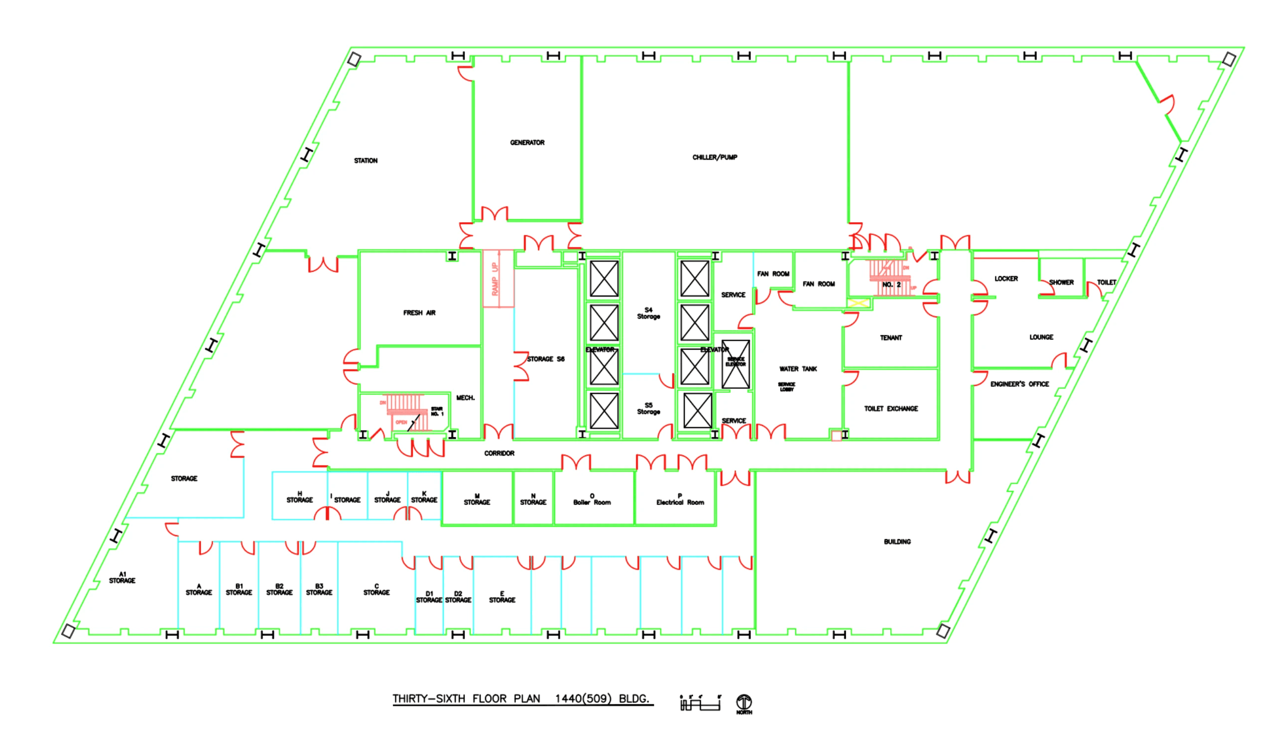
  • How to read engineering drawings, schematics, and manuals

  • Ordering, revising, and updating 2D and 3D graphics for data visualization

GUI Setup Process

The Standard GUI Process for Control Systems

Setting up graphics for controls systems typically involves three major phases:

Analyze engineering drawings and prepare UI assets

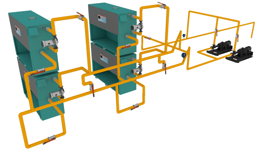
To generate custom 2D and 3D renderings for the UI, it was necessary to meticulously analyze engineering drawings. This process ensured accuracy and identified relevant data points associated with zones or equipment parts.

Access data points setup by Controls Technicians

Controls technicians program devices within the HVAC system to maintain set points and enable automation. To access these points, establishing a connection to the controllers and routing them to the supervisor, which hosts the GUI, was imperative.

Implement UI template and connect elements to data points

Upon connecting the supervisor to the controllers, the GUI template and custom graphics are uploaded. Subsequently, data points are linked to the GUI and thoroughly tested for proper functionality. Once all data points and toggles prove functional, the interface is published to the client.

Preparing Accurate Graphics

Creating Precision Graphics for Accurate Data Visualization

Perform an on site job walk to analyze systems and layouts

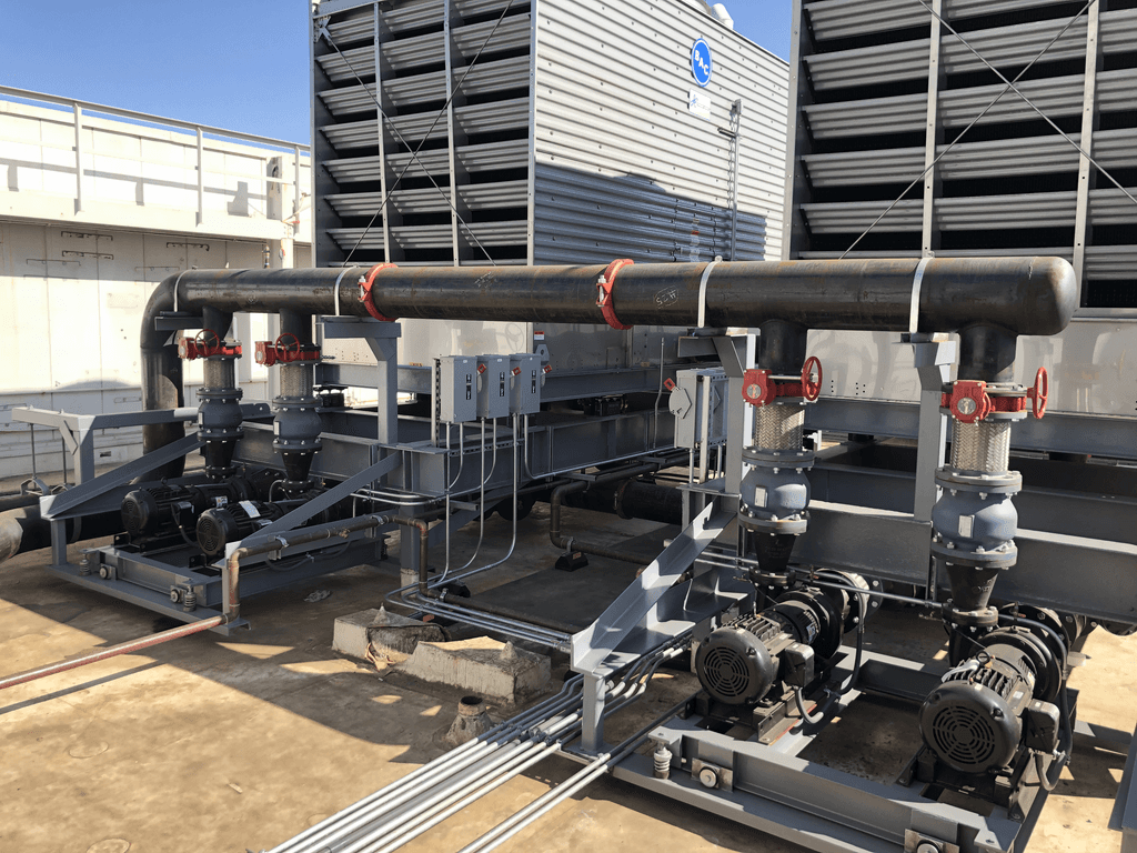
Frequently, mechanical drawings were outdated, failing to accurately depict current building layouts or system configurations. To ensure accurate data visualization, on-site evaluations became crucial, requiring a direct assessment of the structures or systems.

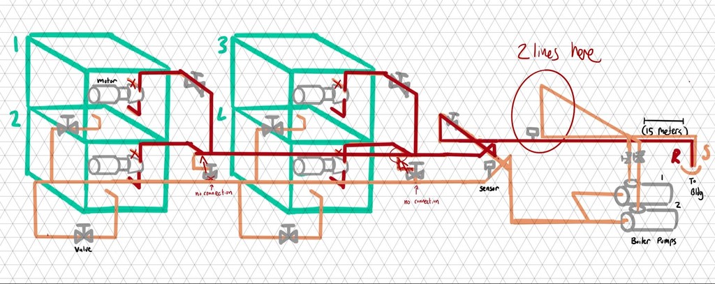
Take photos/videos and draw technical mock ups for graphics

Certain contracts lacked the necessity for certified engineering drawing revisions at the time of construction. To guarantee accurate visualization of equipment, system layouts, and building structural layouts in the graphics, it was essential to create mockups for reference in achieving proper data visualization.

Create or order custom graphics for GUI implementation

Utilizing technical mock-ups and reference photos/videos, the creation of renders was outsourced to a contractor or freelance 2D/3D artist. This outsourcing strategy aimed to streamline workflows and expedite production time.

Redesigning the GUI

Modernizing an Outdated GUI Template

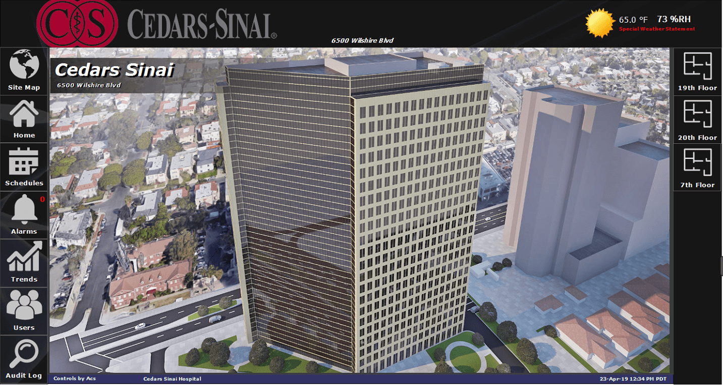
The GUI deployed by ACS, created in the early 2000's

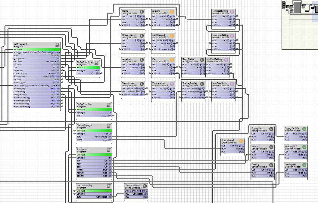
The ACS controls systems GUI, in existence for over a decade upon my arrival, featured large iconography and a template built within Niagara 4 Tridium, lacking built-in CSS capabilities and only functioned at low resolutions.

Old

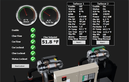
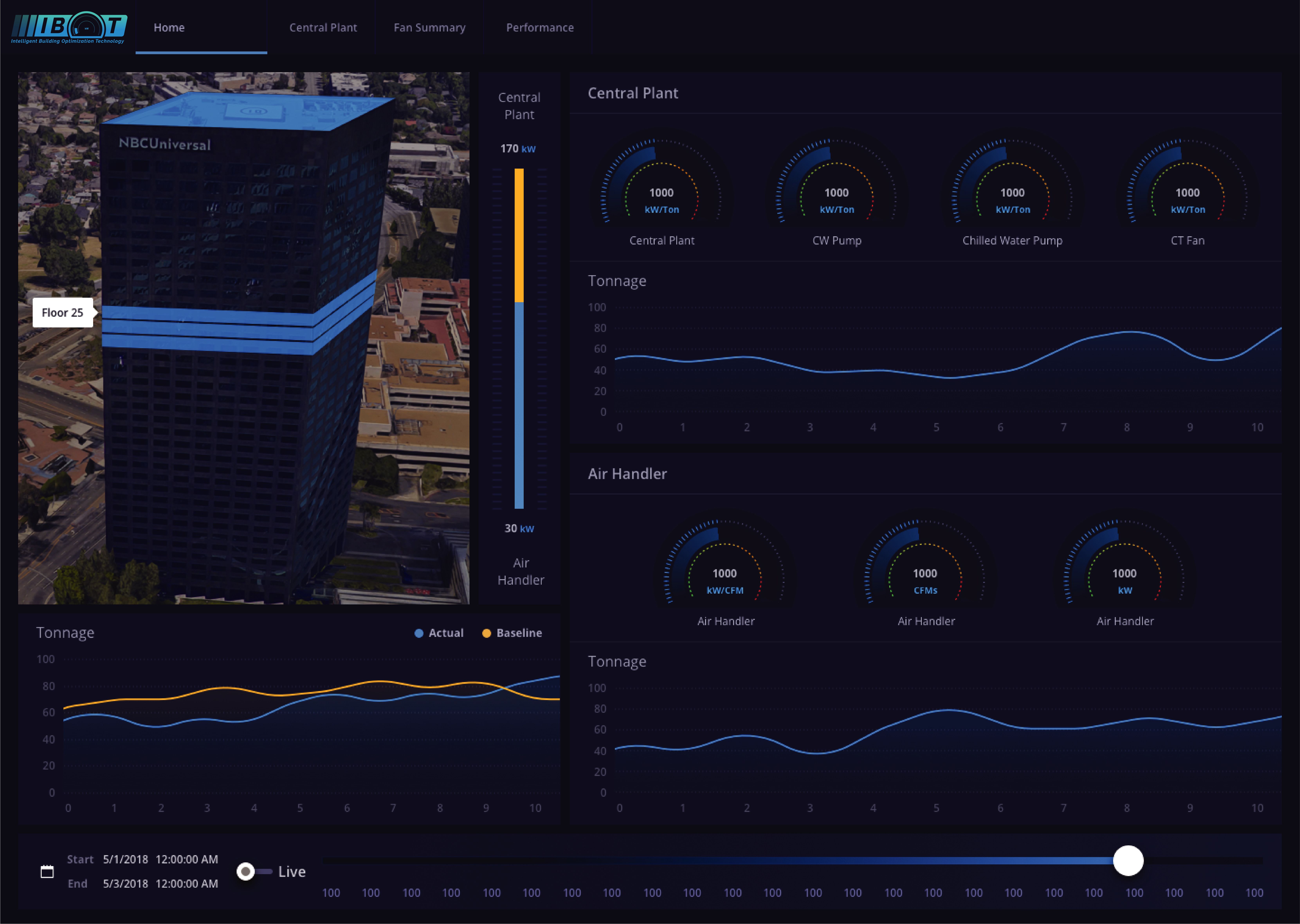
The redesigned GUI, utilizing Eclypse Designer

After familiarizing myself with the current GUI, I obtained Eclypse Designer certification in San Francisco. This software, a Niagara 4 Tridium plugin, allowed for full HTML, CSS, and JS functionality. Leveraging these capabilities, I developed a versatile component library and template package for seamless integration into existing workflows.

New

Conclusion

Takeaways

My time as an HVAC controls GUI designer imparted invaluable lessons that shaped my professional trajectory towards studying UX design. Designing interfaces within the HVAC domain honed my technical skills, requiring attention to detail for accurate data visualization.


I learned to navigate challenges such as revising outdated engineering drawings, performing on-site evaluations and the creation of accurate mockups. Gaining the Eclypse Designer Certification further expanded my capabilities, allowing for comprehensive HTML, CSS, and JS functionality.


Performing constant iteration with the GUI template in Niagara 4 Tridium introduced me to the importance of adaptable design frameworks. These experiences underscored the critical role of user-centric design, inspiring me to delve deeper into UX design studies to leverage this newfound perspective for creating more intuitive and user-friendly interfaces in diverse technological landscapes.
Ready to bring an idea into reality?

© JPN Visual 2023

Ready to bring an idea into reality?

© JPN Visual 2023

Ready to bring an idea into reality?

© JPN Visual 2023